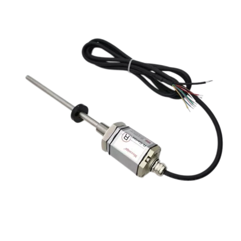
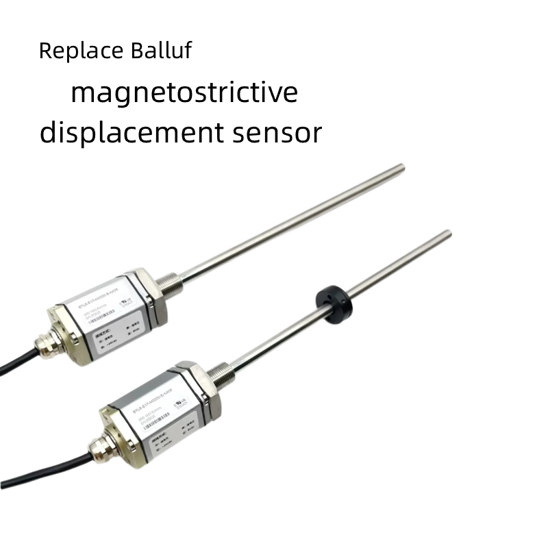
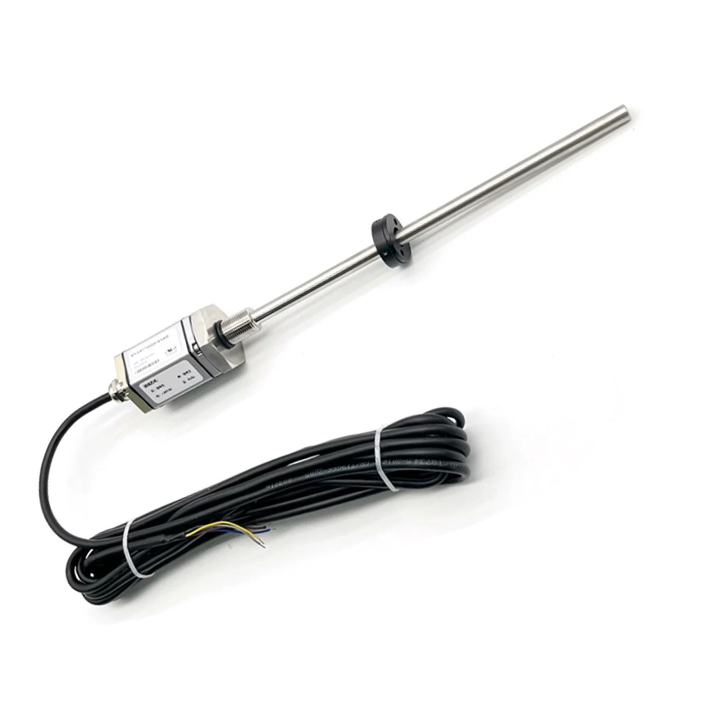
Magnetostrictive Displacement Sensor
Series R
R(H/P/F)C Construction
Note: Do not open the sensor housing arbitrarily; otherwise, the product warranty may be voided.
Operating Instructions
Status Indication / Fault Analysis
The magnetostrictive displacement sensor is used for displacement detection of moving mechanisms. Select magnets matching the magnetostrictive displacement‑sensing electronic components according to the selection specifications for detection in various applications. During operation, ensure cables, connectors and magnets are original manufacturer‑supplied parts.
Analog Output LED Indicators
| Green LED |
Red LED |
Function |
| ON |
OFF |
Normal operation |
| OFF |
ON |
Magnet out of effective stroke range |
| OFF |
ON |
Magnet not detected |
SSI LED Indicators
| Green LED |
Red LED |
Function |
| ON |
OFF |
Normal operation |
| ON |
ON |
Magnet out of effective stroke range or magnet not detected |
| Blinking |
ON |
Programming mode |
Safety Precautions
Read this manual thoroughly before power‑on. Confirm the sensor cable outlet type and pin signal definitions, and perform correct electrical wiring to prevent sensor damage upon power‑up or unintended equipment actions.
During installation and operation, avoid high‑power equipment such as welding machines from feeding current into the sensor circuit. If abnormal sensor readings or obvious physical damage (e.g. dents or deformation) is observed, stop use immediately. Contact the manufacturer to verify sensor condition before resuming operation.
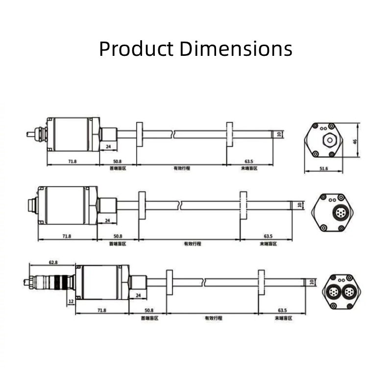
Installation Dimensions
- Front dead zone: 30 mm
- Effective stroke: selectable from 25‑8000 mm
- Rear dead zone: 60 mm
- Standard thread: M18×1.5
- Custom threads: M20×1.5 or 3/4‑1G UNF‑3A
For slider‑magnet versions: Front dead zone:28 mm; Effective measuring range customizable; Rear dead zone:66 mm.
Electrical Interface
Analog Output
6‑pin circular connector (viewed facing sensor)
| Pin No. |
Cable Color Variant 1 |
Cable Color Variant 2 |
Function Definition |
| 1 |
Blue |
Grey |
Magnet position signal + |
| 2 |
Green |
Pink |
Magnet position signal − |
| 3 |
Yellow |
Yellow |
Reserved |
| 4 |
White |
Green |
Reserved |
| 5 |
Red |
Brown |
+24 Vdc ±20% Power supply |
| 6 |
Black |
White |
0 Vdc supply return |
8‑pin circular connector (viewed facing sensor)
| Pin No. |
Cable Color Variant 3 |
Function Definition |
| 1 |
Yellow |
Current output |
| 2 |
Grey |
0 Vdc (current / voltage loop) |
| 3 |
Pink |
— |
| 4 |
Red |
Reserved |
| 5 |
Green |
— |
| 6 |
Blue |
0 Vdc supply return |
| 7 |
Brown |
+24 Vdc ±20% Power supply |
| 8 |
White |
Reserved |
MODBUS
6‑pin circular connector (viewed facing sensor)
| Pin No. |
Cable Color Variant 1 |
Cable Color Variant 2 |
Function Definition |
| 1 |
Blue |
Grey |
Reserved |
| 2 |
Green |
Pink |
Reserved |
| 3 |
Yellow |
Yellow |
Magnet position signal − |
| 4 |
White |
Green |
Magnet position signal + |
| 5 |
Red |
Brown |
+24 Vdc ±20% Power supply |
| 6 |
Black |
White |
0 Vdc supply return |
MODBUS + Analog (Dual‑signal Output)
6‑pin circular connector (viewed facing sensor)
| Pin No. |
Cable Color |
Function Definition |
| 1 |
Grey |
Reserved |
| 2 |
Pink |
Reserved |
| 3 |
Yellow |
Magnet position signal − |
| 4 |
Green |
Magnet position signal + |
| 5 |
Brown |
+24 Vdc ±20% Power supply |
| 6 |
White |
0 Vdc supply return |
SSI Interface
7‑pin circular connector (viewed facing sensor)
| Pin No. |
Cable Color Variant 1 |
Cable Color Variant 2 |
Function Definition |
| 1 |
White |
Grey |
Data (−) |
| 2 |
Yellow |
Pink |
Data (+) |
| 3 |
Blue |
Yellow |
Clock (+) |
| 4 |
Green |
Green |
Clock (−) |
| 5 |
Red |
Brown |
+24 Vdc ±20% Power supply |
| 6 |
Black |
White |
0 Vdc supply return |
| 7 |
— |
— |
Not connected |
8‑pin circular connector (viewed facing sensor)
| Pin No. |
Cable Color Variant 3 |
Function Definition |
| 1 |
Yellow |
Clock (+) |
| 2 |
Grey |
Data (+) |
| 3 |
Pink |
Clock (−) |
| 4 |
— |
— |
| 5 |
Green |
Data (−) |
| 6 |
Blue |
0 Vdc supply return |
| 7 |
Brown |
+24 Vdc ±20% Power supply |
| 8 |
White |
Reserved |
Application Environment
This is a magnetic‑type measuring sensor. Keep strong magnetic fields away from the sensor to avoid measurement interference.
Route displacement output signal cables away from power cables, high‑current conductors and strong pulse interference sources.
Ensure on‑site operating conditions including temperature and vibration stay within the sensor’s rated specifications.
Installation
Sensor installation includes mounting of sensor body, magnet and cable fixation.
Sensor body mounting options: threaded mounting, clip‑on mounting with fixed supports.
Before installation, confirm intact packaging; check that the sensor rod is free of obvious bending or impact damage. Mount the sensor body according to your mounting method.
When installing the magnet, use the supplied magnetic isolation gasket to guarantee proper magnetic circuit performance.
For connector and cable assembly, perform wiring strictly following the electrical interface table in this manual.
After‑sales Support
In case of sensor malfunction, contact our after‑sales department promptly. Do not attempt disassembly or repair by yourself.

评价
目前还没有评价