
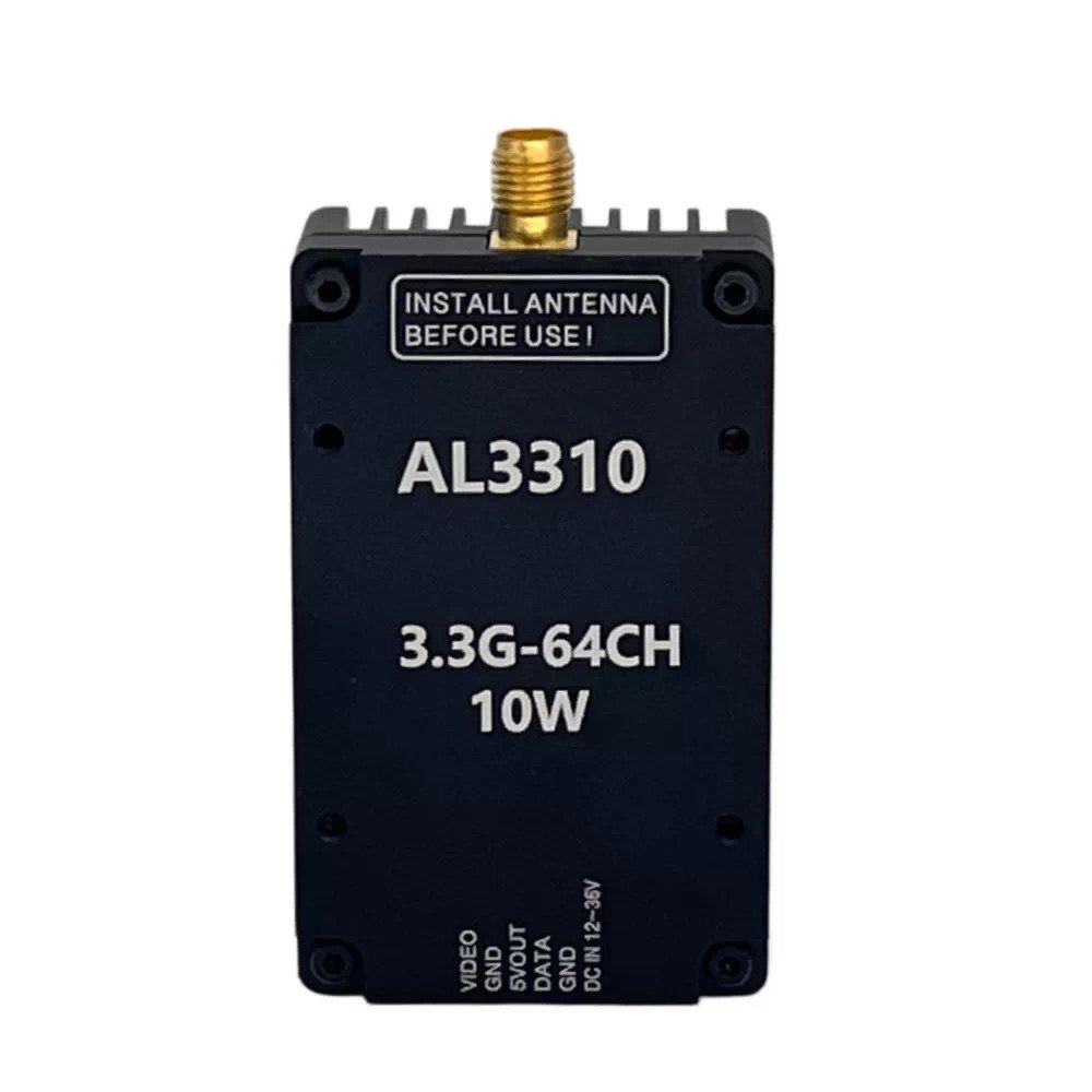
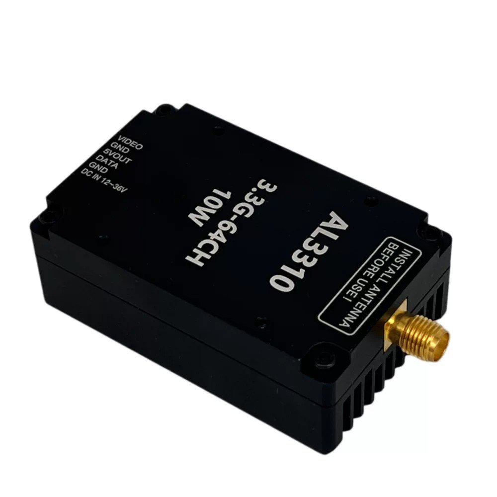

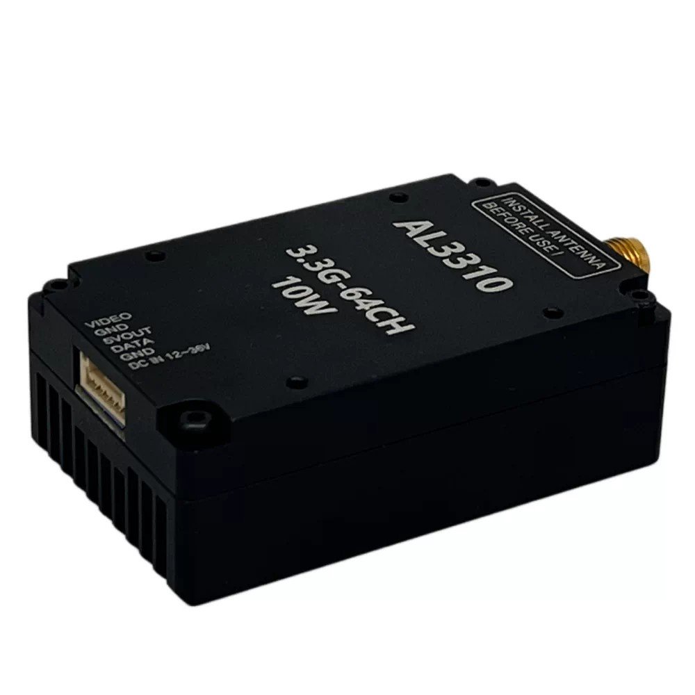
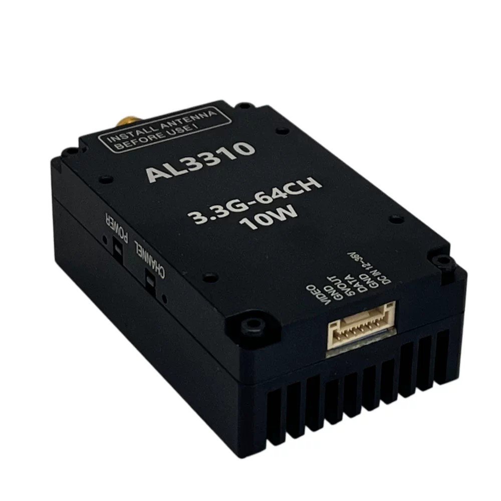
1.Transmitter wiring diagram
| Interface | Definition | Action |
| RF OUT | RF output port | Connect the antenna to receive and transmit the signal |
| Video | Video signal input | Connect to flight control video signal output |
| GND | Power ground | Connect to the power ground terminal (negative) of the device |
| 5VOUT | Voltage output | Internal power supply output 5V/1A |
| DATA | Half-duplex serial port | Connect the flight control board with SMART AUDIO protocol for frequency and power adjustment |
| GND | Power ground | Connect to the power ground terminal (negative) of the device |
| VCC | Power source | Power supply input; power supply range 24–36 V |
2. Transmitter Operation Adjustment Section
The led next to the CHANNAL button is used to display the frequency bands and frequency points. There are 10frequency bands and 8 frequency points in total. Flicker the frequency band first, ficker once to represent the firstfrequency band, and flicker twice continuously to represent the second frequency band. After that, the frequencypoint flashes again at an interval of 1 second. One flash represents the first frequency point, two consecutive flashesrepresent the second frequency point, and three consecutive flashes represent the third frequency point (and so on).
After that, the power enters the regular flash at an interval of 1 secondThe LED Light Next to the POWER Button Is Used to Display the Power, and There Are 5 Powers in Total.Flashing Once Represents LEVEL1 Power, Flashing Twice Represents LEVEL2 Power, Flashing Three TimesRepresents LEVEL3 Power, Flashing Four Times Represents LEVEL4 Power, Flashing Five Times RepresentsLEVEL5 Power. After That, Enter the Regular Flicker of the Frequency Point of the Frequency Band at an Interval of
1 Second.
Transmiter CHANNAL key: short press the FM point and long press the FM band for 3 seconds. POWER
key: short press to adjust the power level.
3.Frequency table
| Band / Channel | CH1 | CH2 | CH3 | CH4 | CH5 | CH6 | CH7 | CH8 |
| 1 Band-A | 3360 | 3380 | 3400 | 3420 | 3440 | 3460 | 3480 | 3550 |
| 2 Band-B | 3200 | 3220 | 3240 | 3260 | 3280 | 3300 | 3320 | 3340 |
| 3 Band-C | 3330 | 3350 | 3370 | 3390 | 3410 | 3430 | 3450 | 3470 |
| 4 Band-D | 3170 | 3190 | 3210 | 3230 | 3250 | 3270 | 3290 | 3310 |
| 5 Band-E | 3320 | 3345 | 3370 | 3395 | 3420 | 3445 | 3470 | 3495 |
| 6 Band-F | 3310 | 3330 | 3355 | 3380 | 3405 | 3430 | 3455 | 3480 |
| 7 Band-G | 3220 | 3240 | 3260 | 3280 | 3300 | 3320 | 3340 | 3360 |
| 8 Band-H | 3060 | 3080 | 3100 | 3120 | 3140 | 3160 | 3180 | 3200 |
4. Description of Remote Control Operation OSD Parameter Setting (serial Port Control Parameter Setting)(SmartAudio 2.1 Protocol)
The image transmission power levels 25 mW, 500 mW, 800 mW, 2.5 W and 5 W of the fight control OSDrespectively correspond to the local transmission power: 25 mW, 500 mW, 800 mW, 2.5 W and 4 W
Reviews
There are no reviews yet.